PwrMini P1 · USER MANUAL

Keep your Mac mini
moving through outages.

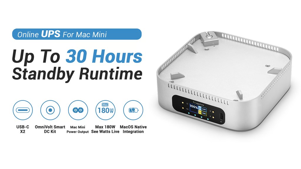
Your Online UPS and DC MicroGrid Hub. Start with first-time setup, and read the complete safety procedure before enabling high-voltage output.

0 ms
True Online architecture
92–95%
DC-direct efficiency
180 W
maximum system power
PwrMini P1 with battery percentage and live power shown on its front display
An integrated power foundation for Mac mini

01 · GETTING STARTED

First use: release the shipping lock

To protect the battery and comply with transport requirements, PwrMini P1 ships in Factory Lock Mode. You only need to complete this procedure once.

  1. 01

    Place the unit securely

    Put P1 on a stable, dry, level surface. Keep all ventilation openings clear.

  2. 02

    Locate the UNLOCK hole

    Turn to the rear panel and find the small hole labeled “UNLOCK.” Do not confuse it with the BIOS reset hole.

  3. 03

    Release the shipping lock

    Insert the supplied SIM ejector tool straight into the hole. Press gently until you feel a clear mechanical click, then release. Do not hold it down.

  4. 04

    Power on

    Press and hold the front Power key for 2 seconds. If a unit has been stored for a long time and does not respond, connect USB-C power for at least 30 minutes, then repeat activation.

Activation tool

Use a rigid SIM ejector tool

A thin needle or soft wire can bend before reaching the internal switch. A straightened, sturdy paper clip can be used if the supplied tool is unavailable.

✓ Confirm the UNLOCK label✓ Press straight with moderate force✓ Feel one distinct click

02 · KNOW YOUR P1

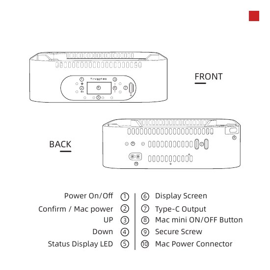
Front and rear panel

Everyday controls are on the front panel. The dedicated Mac power connection, USB-C ports, and mounting hardware are located across the front and rear.

Numbered diagram of the PwrMini P1 front and rear controls
Port locations shown for reference; labeling may vary slightly by production batch.
  1. 01PowerPower on, shut down, wake display
  2. 02Confirm / Mac powerConfirm menus and HV output actions
  3. 03–04Up / DownChange pages, adjust settings, emergency stop
  4. 05Status LEDsBattery, charging, HV, and fault status
  5. 06DisplayBattery, voltage, protocol, and live power
  6. 07USB-C C1 / C2Bidirectional input and output
  7. 08–10Mac mini power linkageMechanical key, security screw, dedicated power

03 · DAILY CONTROLS

Everyday operation at a glance

A

Power on and shut down

  • Power on: hold the Power key for 2 seconds.
  • Wake the display: short-press the Power key.
  • Shut down: hold the Power key through the 3-second countdown. Releasing early cancels shutdown.
  • After HV output is disabled, P1 shuts down automatically after 120 seconds of standby.
B

Three status screens

Use the Up and Down keys to cycle through:

  1. Main dashboard — battery level, source, Mac and USB-C power
  2. Power details — input/output voltage and negotiated protocol
  3. Battery monitor — individual Cell 1–5 voltage
C

Settings menu

From standby, hold the Down key for 2 seconds. Adjust buzzer volume (0 is mute), or view firmware version and serial number.

Hold Confirm for 2 seconds from any settings page to save and exit.

LED STATUS

Priority indicators

Higher-priority states override the normal battery display.

RedFault / over-temperature / short / E-stopWhite flashingHV confirmation in progressOrange steadyHV output activeBlueExternal input / charging

04 · HIGH VOLTAGE OUTPUT

Two confirmations prevent accidental activation.

The dedicated Mac port carries high-voltage DC. Both activation and normal shutdown require two-stage confirmation. Steady orange LEDs mean HV output remains active, even while the display is asleep.

1

Hold Confirm for 2 seconds

The High Voltage Confirmation screen begins a 3-second countdown.

2

Press Confirm again in time

A long beep sounds and the LEDs change from flashing white to steady orange.

3

Use the same sequence to disable

Hold Confirm for 2 seconds, then confirm again during the 3-second countdown.

EMERGENCY STOP

Press Up + Down together

If there is a short circuit, smoke, odor, or abnormal heat, do not navigate menus. P1 immediately cuts HV output, flashes red, and displays “EMERGENCY STOP.”

Recovery: Disconnect the load and external power. Identify and fully correct the cause before a complete power-off/power-on reset. If the fault returns, stop using P1.

COOL & CLEAN

Designed around Mac mini airflow

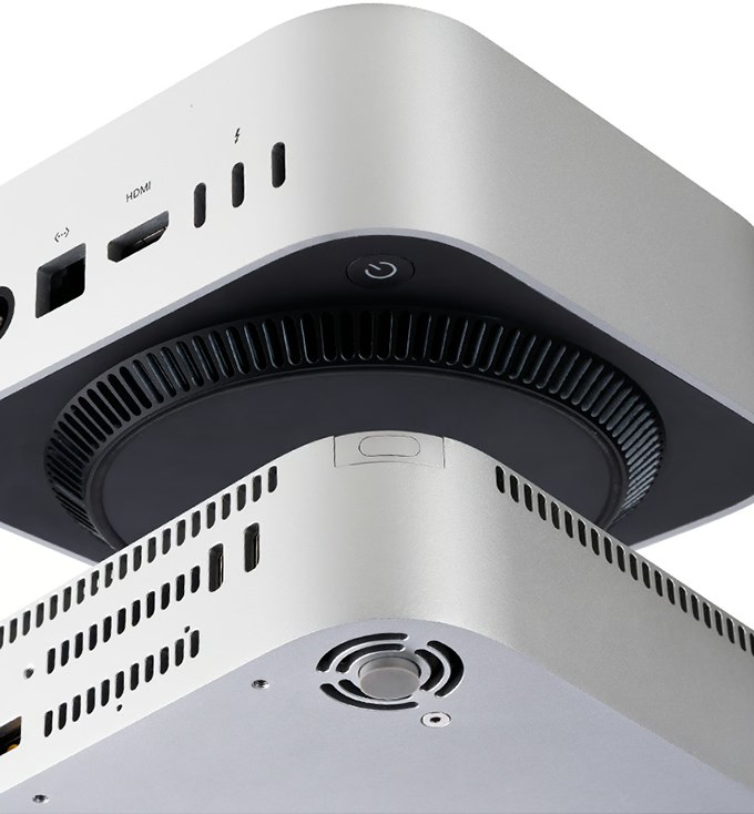
P1 routes air around the Mac mini’s existing intake and exhaust while helping remove its own heat. Align the locating features carefully and leave clear space around every vent.

Never cover the ventilation openingsAvoid soft fabric, closed cabinets, and direct sunlight.
Airflow path through a stacked PwrMini P1 and Mac miniPwrMini P1 mechanical linkage for the Mac mini power button

TACTILE LINK

Power on without lifting your Mac

When correctly aligned, the P1 mechanical linkage extends the Mac mini power button to an accessible position without permanently modifying the computer.

05 · NATIVE MACOS INTEGRATION

Give macOS full awareness of backup power.

P1 reports UPS status through standard USB HID, with no third-party driver. macOS can show battery status and perform a graceful shutdown during an outage.

  1. Use the supplied high-speed USB-C data cable to connect the P1 Console port to a USB-C / Thunderbolt port on Mac mini.
  2. Open System Settings and select Energy Saver (or Battery on some macOS versions).
  3. Confirm that “Trugytex PwrMini P1” and its live battery percentage appear.
  4. Open Shutdown Options… and choose a time-on-UPS or battery-level trigger.

Recommended: Show battery status in the menu bar and perform one controlled external-power disconnect test before relying on the system.

Power
Trugytex PwrMini P1UPS · Connected
89%
Show Battery Status
Shutdown Options…

06 · TECHNICAL SPECIFICATIONS

Power and port specifications

The values below reflect current product documentation. Firmware, protocol support, and supplied cables may change by production batch; follow the labeling on your unit and the latest TrugyTex notice.

Port / itemInputOutput
Dedicated Mac portPowerMatrix Pro DC-to-DC direct-drive architectureDC 120 V / 0.6 A
0.8 A peak
Front USB-C C1PD 100 W max
Pass-through to Mac
45 W max
PD 3.1 / PPS / UFCS / SCP / FCP / AFC / QC
Rear USB-C C2PD 100 W max
Pass-through to Mac
45 W max
PD 3.1 / PPS / UFCS / SCP / FCP / AFC / QC
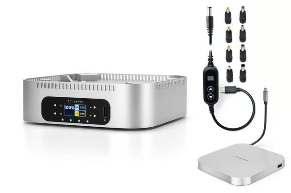
OmniVolt SmartDC Kit5 V / 9 V / 12 V / 20 V · 5525 connector with 8 adapter tips

Dedicated Mac port efficiency: approximately 92–95% by eliminating DC-AC inversion.

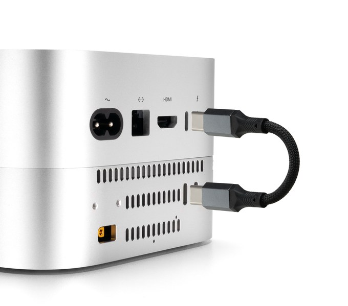
Rear connections with PwrMini P1 and the extension dock stackedPwrMini P1, OmniVolt SmartDC adapters, and extension dock

THREE LAYERS OF DEFENSE

Redundant safety architecture

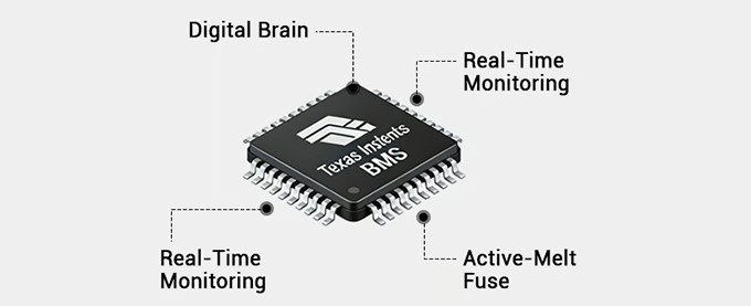
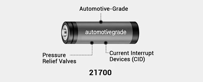
Port-level physical fuses, TI BMS active monitoring, and cell-level hardware safeguards work together. They do not replace proper use: never open the enclosure, short a port, or use an incompatible cable.

Dedicated physical fuses on input and output circuits
Port levelDedicated physical fuses isolate external shorts
TI BMS monitoring and active-melt fuse
System levelTI BMS real-time monitoring and active-melt fuse
21700 cell pressure relief valve and current interrupt device
Cell level21700 pressure relief and current interrupt device

07 · TROUBLESHOOTING

Start here

Confirm that the environment is safe before troubleshooting. If a red fault persists or you notice smoke, odor, or overheating, stop and contact technical support.

I cannot feel a click when releasing the lock

Confirm that you are using the hole labeled UNLOCK. Use a rigid SIM ejector or sturdy paper clip; a thin needle or soft wire may bend before it reaches the internal switch.

The lock clicked, but P1 still does not respond

Long storage may leave the battery below its wake threshold. Connect USB-C power for at least 30 minutes, keep it connected, repeat the UNLOCK step, then hold Power for 2 seconds.

macOS does not detect the UPS

Use a data-capable USB-C cable on the Console port, not a charge-only cable. Reconnect it, check Energy Saver / Battery in System Settings, and try another USB-C / Thunderbolt port.

High-voltage output will not activate

Complete both confirmations: hold Confirm for 2 seconds, then press Confirm again during the 3-second countdown. Successful activation produces a long beep and four steady orange LEDs.

Red LEDs flash or EMERGENCY STOP appears

HV output is locked off. Disconnect external power and every load, then check for a short, over-temperature, liquid ingress, or damaged cable. Reset only after the cause has been fully corrected.

08 · VIDEO GUIDES

See P1 in action

Videos load from YouTube. If embedded playback is unavailable on your network, open the video title directly in YouTube.

09 · TECHNICAL SUPPORT

We are here to help.

Include your serial number, firmware version, LED/display status, power source and cables, plus the steps immediately before and after the issue.